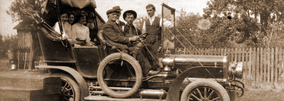
Manufactured by Frank L. Fay and the Greenville Metal Products Company in 1911.
http://www.google.com/patents/US987431
Stay-bolt for steam-boilers.
US 987431 A
-P. J. CONNORQ. STAY-BOLT FOR STEAM BOILERS. APPLICATION IILED D30. 29, 1908.
987,43 1 Patented Mar. 21 1911.
51mm vmmux A commas,
wows
fitter/wag THE NORRIS PETERS co., wnsnmarau, n. c
are
Bron.
PATRICK J’. CONNORS, OF GREENVILLE, PENNSYLVANIA, ASSIGNOR OF ONE-HALF TO FRANK DISLER, OF GREENVILLE, PENNSYLVANIA.
STAY-BOLT FOR STEAM-BOILERS.
To (all whom it may concern:
Be it known that I, PATRICK J. OONNORS, a citizen of the United States, residing at Greenville, in the county of Mercer and State of Pennsylvania, have invented certain new and useful Improvements in Stay- Bolts for Steam-Boilers, of which the following is a specification, reference being had therein to the accompanying drawing.
My present invention relates to an improved stay bolt for steam boilers, the main object of the invention being the provision of a stay bolt, which is provided with means whereby the same may be quickly, economically and properly placed in position, which will retain the boiler sheets or fire box sheets securely together and accommodate itself to the unequal expansion of the boiler plates, the same setting close to the boiler on the outside.
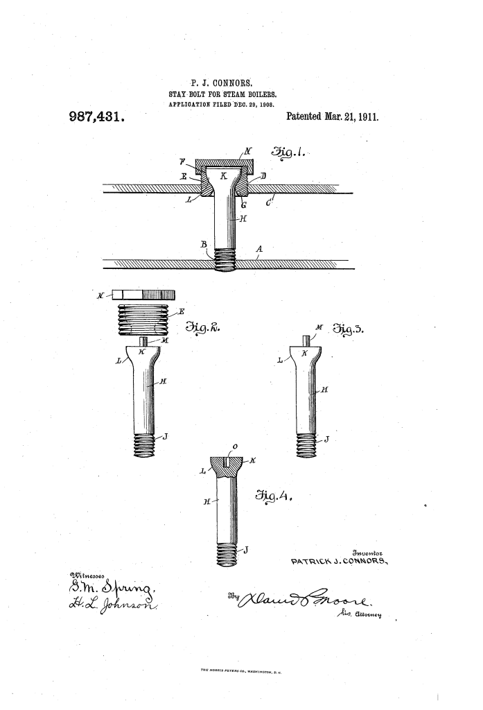
To clearly understand my invention, at tention is directed to the accompanying drawings, in which Figure 1 is a sectional view through the inner and outer plates with my stay bolt in position. Fig. 2 is a side elevation of the complete stay bolt, and its parts removed in order. Fig. 3 is the preferred form of bolt, and Fig. 4 is a modified form.
Referring to the drawings :A designates the inside boiler plate, which is provided with the threaded opening B, and C is the outer plate, which is provided with the enlarged threaded opening D. Secured within the opening D, is the exteriorly threaded sleeve or nipple E, whose interior is pro vided with the upper cupped-shaped socket or seat F, terminating in the lower outwardly curved and rounded annular rim or abutment G. The said seat is positioned at a point nearer the inner end of the sleeve E than the outer end thereof and in a plane with the center of the outer boiler plate C, when the device is assembled.
My stay bolt H, consists of the body portion having the lower threaded end J, which Specification of Letters Patent.
Application filed December 29, 1908.
Patented Mar. 21, 191.1. Serial No. 469,827.
is adapted to pass through the opening D, and be secured in the opening B, as clearly shown in Fig. 1, the head K, of the bolt having the lower rounded or curved portion L, which seats upon the seat F.
In order that the bolt may be properly screwed into position, I have provided several ways, first as shown clearly in Fig. 3, I provide the integral squared lug M, which is formed centrally of the upper or outer face of the head, the same when the bolt is seated, being broken off, so the cap N, may be secured in place, as shown in Fig. 1. The bolt shown in Fig. 4t, is provided with the squared socket O, or may be provided with spanner openings, for the insertion of a tool to turn the bolt.
From the foregoing description, it will be seen that the peculiarly shaped sleeve or nipple E, provides a seat and also allows the bolt to be moved freely in all directions, thus taking up all directions of expansion and contraction, and providing a strong, effective, and cheap flexible stay bolt and fastening means therefor.
What I claim, as new, is
In combination with a stay bolt having a threaded inner end and a head upon the other end thereof, said head having a rounded shouldered portion adjacent to the bolt and provided with a flat outer face, said flat outer face being further provided with a square central lug projecting therefrom whereby the bolt is screwed. in place, said lug being adapted to be sheared off even with the flat face, of a removable bushing detachably fitted in an outer boiler plate and provided with a passage-way therethrough, an annular shoulder in said passageway forming with said bushing a socket to co-act with the rounded shoulder portion of the bolt head to form a ball and socket joint, said passageway curvedly flaring outwardly from said shoulder in opposite directions to the opposite ends of the bushing, said shoulder being positioned nearer the inner end of the bushing and subbeing limited by the position of the cap upon stantially in the plane of the center of the said bushing. 10 outer boiler plate, and a flat closure ca-p fit- In testimony whereof I afi ix my signature ting exteriorly upon the bushing and over in presence of two witnesses.
and parallel to the top face of the head of the PATRICK J. CONNORS.
bolt and lying spaced from the fiat -face of the \Vitnesses:
bolt whenthe cap is screwed down; upon the PA’lR I-CK GLIuLAwI-IAK,
bushing, and a side movement of the bolt JAMES M: CONNELLY.
Copies of this patent may be obtained for five cents each, by addressing the: ‘Gommissioner of Patents, Washington, D. C.
Referenced by
Citing Patent Filing date Publication date Applicant Title
US4124321 * Apr 5, 1977 Nov 7, 1978 B.B.R. Australia Pty. Ltd. Adjustable tie rod holder
* Cited by examiner
Classifications
Cooperative Classification F22B7/16


TrackBack URL
https://www.karenfurst.com/blog/connors-stay-bolt/trackback/